PURPOSE:
The purpose of this circuit experiment is to incorporate the usage of a transistor and a motor.
EQUIPMENT:
 In this circuit, 3 new parts were introduced, Transistor Toy Motor and Diode. The transistor is to control a circuit that's carrying higher current and voltage from the microcontroller (operates like an electronic switch). The one used for this circuit is a NPN transistor. It's designed for switching high-current loads. It has three connections, the base, the collector, and the emitter. The base is connected to the microcontroller's output. The high-current load (i.e. the motor or light) is attached to its power source, and then to the collector of the transistor. The emitter of the transistor is connected to ground.
 A DC motor spins when a current is passed through it. A DC motor was attached to the collector of the transistor. Most motors will require more strength of an electric current than the microcontroller can supply, so sometimes you might need to add a separate power supply as well. If the motor you are using runs on around 9V, you could use a 9V battery. The ground of the motor power supply connects to the ground of the microcontroller, on the breadboard.
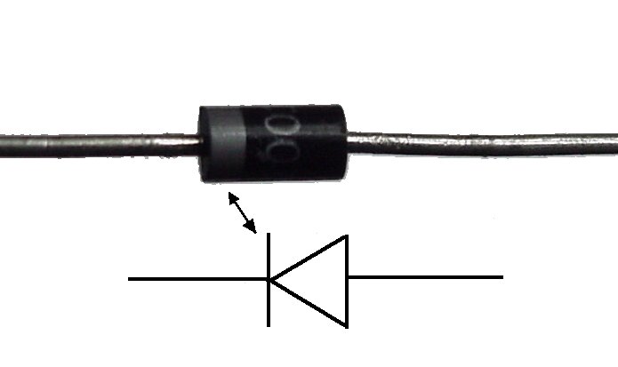 Finally, a diode was added in parallel with the collector and emitter of the transistor, pointing away from ground. The diode is used to protect the transistor from back voltage generated when the motor shuts off, or if the motor is turned in the reverse direction.
EQUIPMENT:
· 1 x Toy Motor
· 1 x Diode(1N4001)
· 1 x 10k Ohm Resistor
· 1 x Transistor P2N2222AG(TO92)
· 7 x Wires (any color)
· 1 x CIRC-03 Breadboard Sheet
· 1 x Arduino Uno
· 1 x Breadboard
· 1 x USB cable
PROGRAM DETAILS:
In this circuit, 3 new parts were introduced, Transistor Toy Motor and Diode. The transistor is to control a circuit that's carrying higher current and voltage from the microcontroller (operates like an electronic switch). The one used for this circuit is a NPN transistor. It's designed for switching high-current loads. It has three connections, the base, the collector, and the emitter. The base is connected to the microcontroller's output. The high-current load (i.e. the motor or light) is attached to its power source, and then to the collector of the transistor. The emitter of the transistor is connected to ground.  A DC motor spins when a current is passed through it. A DC motor was attached to the collector of the transistor. Most motors will require more strength of an electric current than the microcontroller can supply, so sometimes you might need to add a separate power supply as well. If the motor you are using runs on around 9V, you could use a 9V battery. The ground of the motor power supply connects to the ground of the microcontroller, on the breadboard.Finally, a diode was added in parallel with the collector and emitter of the transistor, pointing away from ground. The diode is used to protect the transistor from back voltage generated when the motor shuts off, or if the motor is turned in the reverse direction.
At first, we put the Arduino Holder on the table, attached the Breadboard on the left side and Arduino microcontroller on the right. All the necessary parts for this circuit were gathered. We was decided that attaching the transistor, toy motor, diode and 10k Ohm resistor to the breadboard, respectively and, doing the colorful wiring at the very last would be better so that the other parts don’t come off.
In terms of coding, along with the previous basics few new methods were introduced as shown below.
/*
* motorAcceleration() - accelerates the motor to full speed then
* back down to zero
*/
void motorAcceleration(){
int delayTime = 50; //milliseconds between each speed step
//Accelerates the motor
for(int i = 0; i < 256; i++){ //goes through each speed from 0 to 255
analogWrite(motorPin, i); //sets the new speed
delay(delayTime); // waits for delayTime milliseconds
}
//Decelerates the motor
for(int i = 255; i >= 0; i--){ //goes through each speed from 255 to 0
analogWrite(motorPin, i); //sets the new speed
delay(delayTime); // waits for delayTime milliseconds
}

TIME TO COMPLETE:
This circuit experiment took 22 minutes to complete (17 minutes to create the circuit and 5 minutes to download and upload the code).
RESULTS:
The code was downloaded from (http://ardx.org/CODE03). Fortunately, the program uploaded successfully and the motor was spinning as it was supposed to.
PHOTOS OF PROJECT:
TIPS:
When choosing transistor, make sure you don’t mix it up with the Temperature Sensor which looks very similar to the NPN Transistor. Check the back of the black part to avoid doing this mistake. Also, when you have the transistor make sure you plug in the right way round.
FURTHER WORK:
To take this circuit experiment further, I would like to control the speed of the motor. The Arduino does this by using something called Pulse Width Modulation (PWM). The Arduino can operate its motor really, really fast. Rather than directly controlling the voltage coming from the pin the Arduino will switch the pin on/off very quickly. To do this:
In the loop() section, I’ve to change it to this:
// motorOnThenOff();
//motorOnThenOffWithSpeed();
//motorAcceleration();
PROGRAM MODIFICATIONS:
My program was exactly the same as the one in the Sprakfun Inventor’s Guide except, the only difference is that I shortened the on and off time so that the whole process goes faster.
PROGRAM (with comments):
*/
int motorPin = 9; // define the pin the motor is connected to
// (if you use pin 9,10,11 or 3you can also control speed)
/*
* setup() - this function runs once when you turn your Arduino on
* We set the motors pin to be an output (turning the pin high (+5v) or low (ground) (-))
* rather than an input (checking whether a pin is high or low)
*/
void setup()
{
pinMode(motorPin, OUTPUT);
}
/*
* loop() - this function will start after setup finishes and then repeat
* we call a function called motorOnThenOff()
*/
void loop() // run over and over again
{
motorOnThenOff();
//motorOnThenOffWithSpeed();
//motorAcceleration();
}
/*
* motorOnThenOff() - turns motor on then off
* (notice this code is identical to the code we used for
* the blinking LED)
*/
void motorOnThenOff(){
int onTime = 2500; //the number of milliseconds for the motor to turn on for
int offTime = 1000; //the number of milliseconds for the motor to turn off for
digitalWrite(motorPin, HIGH); // turns the motor On
delay(onTime); // waits for onTime milliseconds
digitalWrite(motorPin, LOW); // turns the motor Off
delay(offTime); // waits for offTime milliseconds
}
/*
* motorOnThenOffWithSpeed() - turns motor on then off but uses speed values as well
* (notice this code is identical to the code we used for
* the blinking LED)
*/
void motorOnThenOffWithSpeed(){
int onSpeed = 200; // a number between 0 (stopped) and 255 (full speed)
int onTime = 2500; //the number of milliseconds for the motor to turn on for
int offSpeed = 50; // a number between 0 (stopped) and 255 (full speed)
int offTime = 1000; //the number of milliseconds for the motor to turn off for
analogWrite(motorPin, onSpeed); // turns the motor On
delay(onTime); // waits for onTime milliseconds
analogWrite(motorPin, offSpeed); // turns the motor Off
delay(offTime); // waits for offTime milliseconds
}
/*
* motorAcceleration() - accelerates the motor to full speed then
* back down to zero
*/
void motorAcceleration(){
int delayTime = 50; //milliseconds between each speed step
//Accelerates the motor
for(int i = 0; i < 256; i++){ //goes through each speed from 0 to 255
analogWrite(motorPin, i); //sets the new speed
delay(delayTime); // waits for delayTime milliseconds
}
//Decelerates the motor
for(int i = 255; i >= 0; i--){ //goes through each speed from 255 to 0
analogWrite(motorPin, i); //sets the new speed
delay(delayTime); // waits for delayTime milliseconds
}
}
REFERENCE:
No comments:
Post a Comment