Tuesday, November 1, 2011

Larger Loads (CIRC-11)

PURPOSE:

The purpose of this circuit experiment is to control a relay using a transistor, and turn on and off two LEDs.

EQUIPMENT:
·         1 x Arduino Holder
·         1 x Arduino Uno
·         1 x Arduino Breadboard
·         1 x Breadboard Sheet (CIRC-11)
·         1 x Diode (1N4001)
·         1 x Transistor P2N2222AG (TO92)
·         1 x Relay (SPDT)
·         1 x Yellow LED
·         1 x Red LED
·         1 x 10k Ohm Resistor (Brown-Black-Orange)
·         2 x 330 Ohm Resistor (Orange-Orange-Brown)
·         Wires (any colour)
Relay (SPDT)
PROGRAM DETAILS:

This circuit lab is a bit of a test, as we combine our knowledge about using transistors in CIRC03 to control a relay. A relay is an useful device and an electrically controlled mechanical switch. Inside the small, black plastic relay box, there is an electromagnet. When the electromagnet gets energized, it causes a switch to trip and it gives a pleasant clicking sound. In this lab, we also use a part called diode which is the electronic equivalent of a one way valve. It allows current to flow in one direction but not the other. For this lab, the current will flow when end with the line is connected to ground.

In terms of coding, no new method or topic was introduced. In fact, the code for this program is very similar to the one from Getting Started (CIRC-01). The pin the LED is connected to is pin 2. The digital pin is set as output using the pinMode() method and digitalWrite(pin, HIGH/LOW) method is used to set the LED on/off.

At the beginning, the relay, transistor, resistors, and LEDs were attached respectively on to the Arduino breadboard. The wiring was done at the very end. When we were putting everything together, one of our 330 Ohm resistors snipped.  Then we got a new one and this time, we were being extra careful with it since it’s so fragile and easy to break off.

TIME TO COMPLETE:

15 minutes to build, 6 minutes to code.

RESULTS:

At first, we couldn’t hear any clicking sound and we realized this was because the transistor or the coil portion of the circuit isn’t quite working. We checked the transistor to see if it is plugged in the right way. We realized that it wasn’t plugged in the right way so we fixed it, and finally our circuit worked as it was supposed to.

PHOTOS OF PROJECT:


TIPS:

The example code uses pin 13 and this lab has the relay connected to pin 2. If nothing happens after your program is uploaded, then check to see if you changed pin 13 to pin 2 in the code.

FURTHER WORK:

For further work, I would like to control a motor. In CIRC-03, we learned how to control a motor using a transistor. However, if you wish to control a larger motor then using a relay would be the right option. This can be done very easily by removing the red LED, and connecting the motor in its place. (Don’t forget to bypass the 330 Ohm resistor).

PROGRAM MODIFICATIONS:

My program is the same as the program in Sprakfun Inventor’s Guide (Page 28 and 29), and same as the one from http://ardx.org/CIRC11 . However, when I was copying the code from File > Examples > 1.Basic > Blink, I made a small change in the code. The small change is that I changed pin 13 to pin 2 because our relay was connected to pin 2.

PROGRAM (with comments):

/*
  Blink
  Turns on an LED on for one second, then off for one second, repeatedly.
  The circuit:
 * LED connected from digital pin 13 to ground.
  * Note: On most Arduino boards, there is already an LED on the board
 connected to pin 13, so you don't need any extra components for this example.
 
 Created 1 June 2005
 By David Cuartielles
 http://arduino.cc/en/Tutorial/Blink
 based on an orginal by H. Barragan for the Wiring i/o board
 */

int ledPin =  2;    // Relay connected to digital pin 2   <-----Change this to pin 2

// The setup() method runs once, when the sketch starts

void setup()   {               
  // initialize the digital pin as an output:
  pinMode(ledPin, OUTPUT);    
}

// the loop() method runs over and over again,
// as long as the Arduino has power

void loop()                    
{
  digitalWrite(ledPin, HIGH);   // set the LED on
  delay(1000);                  // wait for a second
  digitalWrite(ledPin, LOW);    // set the LED off
  delay(1000);                  // wait for a second
}

REFERENCE:


Monday, October 31, 2011

Temperature (CIRC-10)

PURPOSE:

To measure the temperature with a complicated IC (integrated circuit).

EQUIPMENT:
·         1 x TMP36 Temperature Sensor
·         1 x CIRC-10 Breadboard Sheet
·         5 x Wire (any colour)
·         1 x Arduino Holder
·         1 x Arduino
·         1 x Breadboard

PROGRAM DETAILS:


A Temperature Sensor. (Image link)

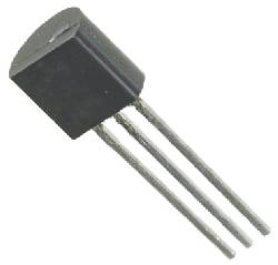
In this circuit experiment, the phenomena we measure with our Arduino is the temperature with the help of a device called IC (integrated circuit). It is very similar looking to our P2N2222AG transistors. It has three pin’s, ground, signal and =5 volts, and is easy to use. It can output 10 millivolts per degree centigrade on the signal pin. There is a 500 mV offset to allow measuring temperatures below the freezing level.

This is the first circuit so far that uses the Arduino’s IDE serial monitor. In the code, the Serial.begin(number) method is used to make a serial connection with the computer. This method also helps determine the speed at which the Arduino sends information, and how fast the computer reads it. A speed of 9600 kilobits per second is chosen to read information because 9600 kilobits/second is the fastest speed at which the Arduino can read information. The Serial.println(temperature) is another method used to program this circuit. This method prints the received information (results) on to the serial monitor. Moreover, some mathematical operations and calculations are done in this circuit to convert temperature units. The variable float is also introduced here for floating point math (decimals). It takes 4 bytes of RAM and has a range between -3.4028235E+38 and 3.4028235E+38.

As a final point, we put the circuits together simply. We gathered the parts we need. Picking the temperature sensor was a little confusing since it’s identical to the P2N2222AG transistor so, we checked to see if the chip has a TMP36 printed on it or not. The wiring was done as instructed in the CIRC-10 Breadboard Sheet.

TIME TO COMPLETE:

4 minutes to build, 10 minutes to program.

RESULTS:


Monitor showing the temperature errors
Our programming took over 10 minutes because our Temperature Sensor wasn’t working properly. At first, when the program was running it was giving us really low negative numbers starting from -50 and it went up to +200. So we quickly took out the temperature sensor, keeping in mind that it can burn our hand since it’s too hot. Then we replaced the previous temperature sensor with a new temperature sensor. We did this 3 times in total but still unexpected, undesired degrees were outputted on the monitor. At last, Mr. Kee came in and concluded that it won’t work because of some unknown programs with the temperature sensor.


PHOTOS OF PROJECT:

CIRC-10 Arduino Circuit

TIPS:

1)      Sometimes, gibberish is displayed on the screen because the serial monitor is receiving data at a different speed than expected. To fix this issue, mouse click the pull-down box that reads “*** baud* and change it to “9600 baud”.

2)      If temperature value is unchanging, try pinching the temperature sensor with your fingers to heat it up or press a bag of ice against it to cool it down.

3)      When working with a partner or in a team, one must be co-operative, responsible and reliable. He/she should also have patience, teamwork skills and excellent communication skills. If you carry these qualities in you then you can work on anything with anyone, anywhere at any time!

FURTHER WORK:

There are four awesome things you can do to make your program better such as, Outputting voltage, Outputting degrees Fahrenheit, More information output, and Changing the serial speed. I would like to output degrees Fahrenheit and to do this, I need to use the formula (F = C * 1.8) + 32. I would also have to add the line temperature = (((temperature – 0.5) * 100)*1.8) + 32; before Serial.println(temperature);.

PROGRAM MODIFICATIONS:

My program is identical to the program from:

PROGRAM (with comments):

/*     ---------------------------------------------------------
 *     |  Arduino Experimentation Kit Example Code             |
 *     |  CIRC-10 .: Temperature :. (TMP36 Temperature Sensor) |
 *     ---------------------------------------------------------
 *  
 *  A simple program to output the current temperature to the IDE's debug window
 *
 *  For more details on this circuit: http://tinyurl.com/c89tvd
 */

//TMP36 Pin Variables
int temperaturePin = 0; //the analog pin the TMP36's Vout (sense) pin is connected to
                        //the resolution is 10 mV / degree centigrade
                        //(500 mV offset) to make negative temperatures an option

/*
 * setup() - this function runs once when you turn your Arduino on
 * We initialize the serial connection with the computer
 */
void setup()
{
  Serial.begin(9600);  //Start the serial connection with the copmuter
                       //to view the result open the serial monitor
                       //last button beneath the file bar (looks like a box with an antenae)
}

void loop()                     // run over and over again
{
 float temperature = getVoltage(temperaturePin);  //getting the voltage reading from the temperature sensor
 temperature = (temperature - .5) * 100;          //converting from 10 mv per degree wit 500 mV offset
                                                  //to degrees ((volatge - 500mV) times 100)
 Serial.println(temperature);                     //printing the result
 delay(1000);                                     //waiting a second
}

/*
 * getVoltage() - returns the voltage on the analog input defined by
 * pin
 */
float getVoltage(int pin){
 return (analogRead(pin) * .004882814); //converting from a 0 to 1024 digital range
                                        // to 0 to 5 volts (each 1 reading equals ~ 5 millivolts
}

REFERENCE:

Sparkfun Inventor’s Guide. Page 26 and 27.


Light (CIRC-09)

PURPOSE:

To turn a LED on using a Photo Resistor (light based resistance). 

EQUIPMENT:

·         1 x Photo-Resistor
·         1 x Yellow LED
·         1 x 10k Ohm Resistor
·         1 x 330 Ohm Resistor
·         1 x CIRC-09 Breadboard Sheet
·         6 x Wire (any colour)

PROGRAM DETAILS:

A Photo Resistor (Image Link)

The new part introduced in this program is called the photo resistor which is a light based resistance. Photo resistor is a device that produces a variable resistance dependant on the on the amount of incident light. It has 2 leads and it looks like a little disk with a transparent top and a curvy line underneath. They are good for environmentally controlled experiments. The principles we use for a photo resistor is same as the potentiometer’s principles except the fact that a photo resistor is light based whereas, the potentiometer is a twist based resistance.

In terms of coding, no new methods were introduced. What the program did is simply change the intensity of an LED based on the amount of light incident on the photo resistor. For this circuit, the pin the led got connected to is pin 9 because here, we are controlling brightness so we use one of the PWM (Pulse Width Modulation Pins).  The methods analogRead() and analogWrite() were also used in this lab to read/write the light level.

With the help of the CIRC-09 Breadboard Sheet, we put together this simple circuit. The Arduino Uno senses voltage and it can’t directly sense resistance so we had to set up a voltage divider. The voltage at the sensing pin is always assessable, but our purpose is sensing relative light so we experimented with the values to see what works for us.

TIME TO COMPLETE:

It took us exactly 8 minutes to build the circuit and about 6 minutes to code.

RESULTS:

The circuit was set up well and the program was coded, downloaded the right way. Hence, our circuit worked effectively in our first try. A low value occurred when the sensor was well lit and a high value occurred when it was in darkness.

PHOTOS OF PROJECT:


Due to the lack of Varshini's photography skills,
the LED in the above pictures is not lighting up.
TIPS:

Don’t forget that a photo resistor needs to be in a voltage divider before it provides a useful input.

After you program your circuit, if the LED remains dark then pull it up and give it a twist.

If you're in a room that is either too bright or dark, your circuit might not work. Try turning the light on or off to see if it works or, take a flashlight and give that a try.

FURTHER WORK:

To make my program better, I would like to reverse the response of the circuit. This can be easily done by changing the analogWrite(ledPin, lightLevel); -----> analogWrite(ledPin, 225 - lightLevel); . In addition, rather than controlling the brightness of the LED in response to light, I would like to turn it on and off based on a threshold value. This can be obtained by changing the loop() code with:

void loop()
 {
    int threshold = 300;
    if(analogRead(lightPin) > threshold){
       digitalWrite(ledPin, HIGH);
    }else{
       digitalWrite(ledPin, LOW);
    }
}
  
PROGRAM MODIFICATIONS:

My program is exactly the same as the one from:

PROGRAM (with comments):

/*
 * A simple programme that will change the intensity of
 * an LED based  * on the amount of light incident on
 * the photo resistor.
 *
 */

//PhotoResistor Pin
int lightPin = 0; //the analog pin the photoresistor is
                  //connected to
                  //the photoresistor is not calibrated to any units so
                  //this is simply a raw sensor value (relative light)
//LED Pin
int ledPin = 9;   //the pin the LED is connected to
                  //we are controlling brightness so
                  //we use one of the PWM (pulse width
                  // modulation pins)
void setup()
{
  pinMode(ledPin, OUTPUT); //sets the led pin to output
}
 /*
 * loop() - this function will start after setup
 * finishes and then repeat
 */
void loop()
{
 int lightLevel = analogRead(lightPin); //Read the
                                        // lightlevel
 lightLevel = map(lightLevel, 0, 900, 0, 255);
         //adjust the value 0 to 900 to
         //span 0 to 255


 lightLevel = constrain(lightLevel, 0, 255);//make sure the
                                           //value is betwween
                                           //0 and 255
 analogWrite(ledPin, lightLevel);  //write the value
}

REFERENCE:
·         http://ardx.org/VODI
·         http://ardx.org/VIDE09